What does a high time constant for RC circuit mean?
High RC time constant leads to a lower ripple of the output voltage around its average value. #1 is easy to explain - just recall that high time constant means longer raise/fall time of the voltage in a simple RC circuit. The same applies to this RC filter.
How to derive the resonant frequency from the RLC circuit?
Resonant Frequency Formula – Series Resonance Circuit. The formula for resonant frequency for a series resonance circuit is given as. f = 1/2π√(LC) Derivation: Let us consider a series connection of R, L and C. This series connection is excited by an AC source.
How to solve the series RLC circuit?
- If resistor, inductor, and capacitor are connected in a series AC circuit, the circuit will be called an RLC series circuit.
- The phase difference between voltage and current is adjusted by the difference between capacitive and inductive reactance.
- In the impedance and voltage triangle, quantities are added vectorially.
Why is the RLC series circuit called an acceptor circuit?
Because impedance is minimum and current is maximum, series resonance circuits are also called Acceptor Circuits. In the next tutorial about Parallel Resonance we will look at how frequency affects the characteristics of a parallel connected RLC circuit and how this time the Q-factor of a parallel resonant circuit determines its current ...
What is meant by time constant of a circuit?
Definition of time constant 1 : the time required for a current turned into a circuit under a steady electromotive force to reach to (e-1)/e or 0.632 of its final strength (where e is the base of natural logarithms) specifically : the ratio of the inductance of a circuit in henries to its resistance in ohms.
What is the time constant unit?
The unit for the time constant is seconds (s). R stands for the resistance value of the resistor and C is the capacitance of the capacitor. The Time Constant is affected by two variables, the resistance of the resistor and the capacitance of the capacitor.
What is time constant in RL and RC circuit?
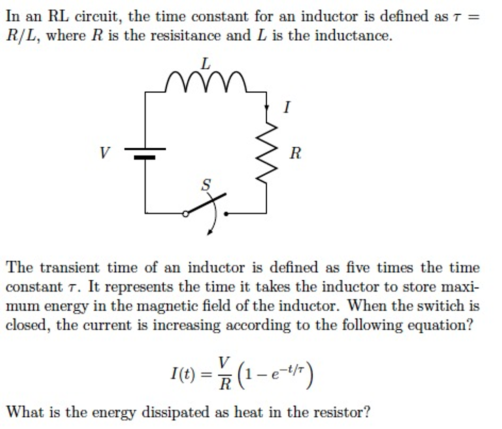
RC AND RL TRANSIENT RESPONSES T = RC. The time constant of an inductor circuit is the inductance divided by the resistance. T = L/R. A time constant is the time needed for a change of 63.2 % in the voltage across a capacitor or the current through the inductor.
How is time constant calculated?
5:017:32How to Measure the Time Constant with an Oscilloscope - YouTubeYouTubeStart of suggested clipEnd of suggested clipBefore. You do that we should probably learn how to calculate the time constant without goingMoreBefore. You do that we should probably learn how to calculate the time constant without going through the math you can do some fancy substitutions. Using the formula for charge Q equals CV and
What is time constant in transient analysis?
About the time constant. The time constant τ (the Greek letter tau) has units of seconds (verify, for both RC and R/L), and it governs the “speed” of the transient response. Circuits with higher τ take longer to get close to the new steady state. Circuits with short τ settle on their new steady state very quickly.Jul 26, 2017
What is time constant in capacitor?
The time constant of a resistor-capacitor series combination is defined as the time it takes for the capacitor to deplete 36.8% (for a discharging circuit) of its charge or the time it takes to reach 63.2% (for a charging circuit) of its maximum charge capacity given that it has no initial charge.
What is the Time Constant?
The time constant – usually denoted by the Greek letter τ (tau) – is used in physics and engineering to characterize the response to a step input of a first-order, linear time-invariant (LTI) control system. The time constant is the main characteristic unit of a first-order LTI system.
Time Constant of an RC Circuit
Let us take a simple RC circuit, as shown below. Let us assume the capacitor is initially uncharged and the switch S is closed at time t = 0. After closing the switch, electric current i (t) starts flowing through the circuit. Applying Kirchhoff Voltage Law in that single mesh circuit, we get,
Universal Time Constant Curve
Because of the identical nature of the transient response in RL and RC circuits, a common graph may represent both, as in figure 2.
Exponential Nature of Time Constant Curve
The universal time constant graph is based on the following equation, which gives the exponential rise in a capacitive circuit and is derived from the calculus:
